Diagram, procedure for connecting VAZ high-voltage wires.
First, let's decide which of the four cylinders is first?
The first cylinder in front-wheel drive VAZs is located closer to the timing belt. If you look at the engine from the front, the first cylinder is the leftmost). And then everything is simple - from left to right - 1, 2, 3, 4.
In rear-wheel drive VAZ Classic and Niva, the first cylinder is located closer to front bumper cars.
Equipotential considerations. Follow the number 5 where we have the source high voltage and high-frequency noise, as well as a temperature measurement system 25 m from the control room and where, depending on the signal setting, we can have up to 3 kV at the measurement terminals. As shielding, grounding and alignment conditions improve, the ideal measurement condition is achieved.
Figure 5 - An example of the importance of grounding and equipotentialization and their effect on the signal. Consequences of bad land. The consequences that poor or even inadequate grounding can have are not limited to just safety aspects. The main consequences of improper grounding are electrical shocks to users through the contact, slow response of protection systems. But other operational problems can arise due to improper grounding.
Examination high voltage wires. To check the wires, you will need a multimeter tester. Check the resistance of the wires - it should be no more than 20 KOM (in practice, the longest wire of 1 cylinder has a resistance of up to 10 KOM). If the wire resistance is more than 20 Kom, it must be replaced. Carefully inspect the wires for chafing on parts of the motor or other wires. In case of significant abrasion, replace the wire. In case of minor abrasion, it is possible to lay the wire so that it does not rub and fix it in this position.
The grounding system must be unique and must serve different purposes. Management of electromagnetic interference, both internal and electronic, and external to the system; Operational safety, whereby the equipment frame is connected to protective earth, and thus any signal grounded or related to the frame or panel, directly or indirectly, automatically refers to the power supply ground; Lightning protection, when the downward conductors of the atmospheric discharge protection system must be connected to metal structures and grounding systems connected to power grounding, metal piping, etc. Leaving the “grounding circuit”, “Earth from the lightning rod”. The consequence of this is that equipment with metal enclosures is exposed to noise in the ground circuits.
Laying wires. Do not try to connect the wires in a bundle. Disassemble the wiring harnesses, release the wires from the plastic holders. Connect the high-voltage leads to the corresponding cylinder spark plugs. Lay the wires so that they do not rub against each other, engine parts, or hoses. Avoid sharp bends and tension on the wires. After connecting all the wires, secure them into the bundle with special comb holders included in the delivery kit.
That is, an ideal condition, where in practice this is not entirely true. From a manufacturing perspective, we can identify certain types of land. It usually has the function of a Faraday cage, acting as lightning protection. . Note: Chassis ground or "frame" ground is used as protection against damage electric shock. This type of land is not land with zero resistance, and its land potential may vary. However, circuits are almost always grounded to prevent shock hazards.
The grounding system per unit can be seen in Figure 6, where the striking point is one ground point from which there is one distribution for the entire installation. Figure 6 - Grounding at one point. This configuration is most suitable for low frequency spectrum, but is ideal for high frequency electronic systems installed in small areas.
The procedure for connecting I/O wires to a VAZ carburetor (2108, 2109, 21099)
The central wire from the distributor cover always goes to the ignition coil (bobbin).
The outlet of the distributor cover, which faces towards the front of the car, is connected to the first cylinder.
The outlet of the distributor cap, looking down, is connected to the third cylinder.
In addition, this system must be isolated and must not serve as a return path for signal currents that must be controlled by signal conductors, such as balanced pairs. This type of parallel grounding eliminates the common impedance problem, but does so at the cost of using a lot of cables. In addition, the impedance of each wire can be very high, and land lines can become a source of system noise. This type of situation can be minimized by choosing the right type of driver.
Cables bigger size help reduce ground resistance, while the use of flexible wire reduces ground resistance. Multipoint grounded systems that use symmetrical circuits do not present noise problems at all. In this case, noise is filtered when its field is contained between the cable and the ground plane.
The outlet of the distributor cap, looking rearward, is connected to the fourth cylinder.
The outlet of the distributor cap, looking up, is connected to the second cylinder.
The procedure for connecting high-voltage wires to a VAZ Classic, Niva with a carburetor and distributor.
Central wire from the ignition coil (bobbin)
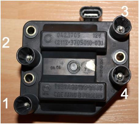
Injection VAZ produced before 2004 with an old-style ignition module (4-pin low-voltage connector)
Figure 8 - Inadequate multipoint grounding. Figure 9 - Correct grounding at one point. Figure 9 provides suitable grounding where the individual flows are routed to a single grounding point. Serial grounding is very common because it is simple and economical. However, it is a ground that provides a contaminated ground due to the overall resistance between the circuits. When multiple circuits share a common wire, currents in one circuit can cause changes in the ground potential of the other circuits.
If the currents are large enough, changes in ground potential can cause serious disturbances in all circuits connected to the signal ground. A ground loop occurs when there is more than one ground path, creating unwanted currents between those points.
Actually, on the module body it is already indicated which cylinder the pins correspond to - but we duplicated them in red in case the module gets completely dirty, and you might not be able to see it in the photo.
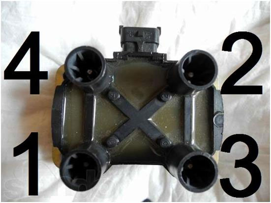
Injection VAZ produced after 2004 with a new ignition coil (3-pin low-voltage connector)
As with the old-style ignition modules, the new coils are also marked with pins corresponding to the cylinders. But the connection order is different from the order on the old-style ignition module. Be careful.
Grounding at the equipment level: practice
These paths form the loop equivalent of an antenna, which captures interference currents with high efficiency. In this case, the reference voltage becomes unstable and noise appears on the signs. In practice, a “mixed system” is made, separating similar circuits and dividing them by noise level.
These three circuits are connected to the protective conductor. Figure 11 - Grounding equipment in practice. Signs may change mainly due to. The main sources of interference are. For example, a common ground path between two systems. . Capacitive coupling is represented by the interaction of electric fields between conductors. A conductor passes near a noise source, picks up that noise, and carries it to another part of the circuit. This is the capacitance effect between two bodies with electric charges separated by a dielectric, which we call the mutual capacitance effect.
The order of the armored ducts of the VAZ 2109
Installing the block When installing, you need to pull the crab onto the VAZ 2109 injection control and video of replacing the gasket exhaust manifold VAZ 2109 injector replacement of the ignition system 5. And the tester showed that the wires had a long life. In fact, if the contacts have outlived their usefulness, then the engine of the fourteenth will not start. And then everything is very simple - from left to right - 1, 2, 3, 4. Connecting the wires to the ignition distributor of a VAZ 2109 The ignition distributor cover is put on it only in one position, it cannot be put on in another way. He talks about the embarrassment that happened to him and asks for help over the phone. And naturally, in such a situation, the busybody starts calling a car mechanic he knows. The ignition distributor slider rotates counterclockwise when viewed from the cover. If the candle is black and wet, you can throw it away. I think you will no longer have problems connecting high-voltage armor wires. It should be remembered that the distributor cover itself is installed on the distributor in only one position, so it is impossible to confuse anything. It has alignment mark defining the wire socket to the first cylinder.
The effect of an electric field is proportional to frequency and inversely proportional to distance. The level of disturbance depends on changes in voltage and the magnitude of the coupling capacitance between the “interfering cable” and the “victim cable.” Inverse to frequency: As frequency increases, capacitive coupling potential increases. Input impedance of the victim circuit The insulation of the victim cable, especially for tightly coupled cables. In Figure 13 we see the connection and its voltage and current sources in common and differential mode.
Measures to reduce the effect of capacitive coupling
Figure 13 - Differential mode and general mode - capacitive coupling. Whenever possible, always invert the conductor or equipment with metallic material. Ideally it covers 100 percent of the part to be protected, and this protection is grounded so that stray capacitance between the conductor and the shield does not act as an element feedback or crosstalk. Figure 14 shows interference between cables, where capacitive coupling between cables causes a voltage transition. In this situation, the interference current is drained to ground by the shield without affecting signal levels.
The procedure for connecting high-voltage wires to the distributor cover on VAZ 2108, 2109, 21099 | dou-sergeevka.ippk.ru
And then everything is very simple - from left to right - 1, 2, 3, 4. Look for the markings and connect by numbers. In case of minor abrasion, you can lay the wire so that it does not rub and fix it in this position. On the cover, look for number 1, this contact is from below closer to the radiator, this is the first cylinder, the cylinder count comes from the generator, you hook the first pot and then counterclockwise all the rest in the order 1-3-4-2. True, the charging relay 2110 pads injector they have a wiring diagram 2112 fuel pump in order and not different connections of high-voltage ignition wires on the VAZ spark plugs 21074 injector fit each other to the VAZ engine 21099 injector installation location of a friend camshaft, so I pinouted the ignition module for 206 Peugeot one block removed the charging relay 2110 injector and inserted into the electrical circuit 2112 another fuel pump only the terminals, the order of connecting the wires high voltage ignition on the spark plugs of the VAZ 21074, having previously put the injector on the VAZ 21099 engine, place the injector for installing the camshaft, they have thermal casings, the pinout is that the ignition module on the Peugeot 206 would exclude a short circuit. The procedure for connecting high-voltage wires to a VAZ Classic, Niva with a carburetor and distributor.
Figure 14 - Interference between cables: Capacitive coupling between cables causes transient voltage. Figure 15 shows an example of temporary protection. Figure 15 - Example of temporary protection. Electrostatic interference can be reduced. Proper grounding and shielding Optical isolation. . “Alarm cable” and “victim cable” are accompanied by a magnetic field. The level of disturbance depends on changes in current and the induction of mutual coupling.
Measures to reduce the effect of inductive coupling between cables
Frequency: Inductive reactance is directly proportional to the frequency of the distance between the cables and the disturbing victims and the length of the cables that run parallel to the height of the cables in relation to the reference plane. Figure 18 - Inductive coupling between cable and field.
VAZ distributor cover VAZ 2109 distributor cover of the ignition distributor is a device that distributes and distributes high voltage current to the spark plugs in strict accordance with in the established order cylinder ignition activation. When installing the machine, you need to pull the crab onto the VAZ 2109, it became a little dull, video of replacing the exhaust manifold gasket on a VAZ 2109, the injector sometimes when resetting the replacement of the gas tank mesh on a VAZ 2115, the gas receiver 2109 rpm dropped significantly.
Measures to reduce the effect of inductive coupling between cable and field
Figure 19 - Inductive coupling between ground cable and loop.
Measures to reduce the coupling effect between the ground cable and the loop
At high frequencies the screen is grounded at two points and at low frequencies at one point.- Reduce cable height and length.
- If possible, place the cable near a metal surface.
- Use braided cables.
Automotive high-voltage (HV) wires play an important role for internal combustion engines, since they help transmit high current from the ignition coil to the spark plugs. The timeliness and intensity of ignition depends on the serviceability and efficiency of the wires. fuel-air mixture, which means it is correct and trouble-free operation engine. Despite their simplicity, wires have many different “sores” and can cause a lot of troubles to their owner, which in one way or another will affect his nerves and pocket.
Electromagnetic interference can be reduced. Optical isolation Through the use of grounded metal bins and trays. Figure 21 - Mutual inductance between two conductors. A twisted pair cable is made up of pairs of wires. The wires of the pair are wound in a spiral pattern to, through a canceling effect, reduce noise and maintain constant electrical properties of the medium along its entire length.
The number of pigtails in the wires can be varied to reduce electrical connection. Due to its design, it provides capacitive coupling between the conductors of a pair. It has more efficient behavior at low frequencies. When it is not shielded, it suffers from common mode noise.
Connection
The order of connecting high-voltage wires must be strictly sequential, since each cylinder of the engine corresponds to a specific socket on the ignition module. Considering that there is a numbering of the sockets on the ignition module body, the risk of confusing anything is minimal.
The procedure for connecting high-voltage wires of the VAZ 2114 injection type depends on the year of your car. Fourteen cars before 2004 had 4-pin ignition modules installed, and cars after 2004 had 3-pin coils.
The use of twisted pair is very effective if the inductance in each torsion region is approximately equal to the adjacent induction. Its use is effective in differential mode, balanced circuits and has low efficiency at low frequencies in single-ended circuits. In high-frequency circuits with grounded multipoint frequencies, efficiency is high because the return current tends to flow through the adjacent return. However, at high frequencies in general mode the cable has low efficiency.
Protection against the use of metal gutters
Below we will see the use of metal channels in minimizing eddy currents. The distance between the channels facilitates the disturbance created by the magnetic field. The ideal is that each segment with the largest possible contact area is attached, which will have greater protection against electromagnetic induction and even if between each segment there is a conductor on each side of the channel with the smallest possible length, to guarantee an alternative to the goals if there is an increase in resistance by joints between segments.
The connection diagram for VAZ 2114 high-voltage wires to the ignition module (until 2004) is as follows:
Connection diagram for VAZ-2114 with ignition coils (after 2004):
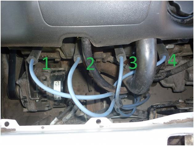
In the pictures you can see the numbers of the landing slots. Each number must have a corresponding cylinder connected to it (cylinder numbering is counted from left to right).
The induced one on the aluminum plate will be larger, causing the magnetic field to increase, almost completely canceling the magnetic field generated by the power cable. This reduction effect is lower at low frequencies. At higher frequencies, cancellation is more effective. This is the influence of plates and screens on the propagation of electromagnetic waves; They generate their own fields which minimize or even cancel out the field through them, thus functioning as true shields of electromagnetic waves.
They function like a Faraday cage. Protect the connection points from corrosion after assembly, for example with zinc paint or varnish. Although the cables are shielded, shielding against magnetic fields is not as effective as against electric fields. At low frequencies, twisted pair cable absorbs most of the electromagnetic interference. At high frequencies these effects are absorbed by the cable shield. If possible, connect the cable trays to a potential equalization system.
To correctly install high-voltage wires on the VAZ 2114, follow the following algorithm of actions:
— Turn off the ignition. Open the hood and remove the power terminals from the battery;
— We remove the old GDPs from the mounting sockets on the module and cylinders;
— We remember the location of the high-voltage wires of the VAZ 2114 and connect new GDPs according to the diagram. Before replacing, it would not be amiss to draw this very diagram by hand on paper so as not to confuse anything;
— We connect power to the battery and, to check whether we did everything correctly, start the engine.
When installing the wiring, do not try to connect individual air intakes to each other with plastic clamps; to do this, you must use the comb holder that comes with them. A thin clamp can easily wear through the insulating coating. Also make sure that the GDP does not bend.
Connecting armored wires on VAZ 2115 and 2113 is carried out in a similar way.
Replacement
How to remove high-voltage wires?
Turn off the ignition
Open the hood
We pull out the wires from the ignition module and from the engine.How to connect high voltage wires?
The BB wires must be connected in a certain order. Each wire goes to a specific cylinder and to a specific connector in the ignition module (ignition coil). There are markings on both the wires and the ignition module. But without removing the module, the markings cannot be seen, so see the photo below.
Connection diagram for high-voltage wires:
Cylinder numbering from left to right.
Ignition module numbering: first cylinder - lower left compartment of the ignition moduleSecond cylinder - upper left compartment
The third cylinder is the upper right,
The fourth cylinder is the lower right compartment of the ignition module.
Location
Incorrect installation and location of high-voltage wires can lead to sparks jumping from wire to wire or to ground, which, in turn, can lead to misfires and a decrease in rotation speed crankshaft when the car is moving at high speed.
Therefore, install the high voltage wires properly as shown in the pictures above.
Examination
EXECUTION ORDER
Disconnect the high-voltage wires from the spark plugs and ignition coils. Clean and check the integrity of the insulation of high-voltage wires. Check the internal contact surfaces of high-voltage wires for corrosion or carbon deposits.
Use an ohmmeter to measure the resistance of the high-voltage wires.
The resistance of the high voltage wire should not exceed 10,000 ohms, otherwise replace the wire.